

4.2.6. Beronet BRI cards
Beronet BRI cards
beroNet offers the BN2S0, BN4S0 and the BN8S0 BRI ISDN cards, a powerful and flexible solution for the Open Source PBX Asterisk.
Together with Asterisk's channel-driver "chan_mISDN", which is covered by the GPL licensing agreement. beroNet channel-driver is based on the new ISDN stack of the new Linux Kernel: mISDN (modular ISDN).
The BNXS0 card series is available with 2, 4 or 8 S0 ports, which can be configured individually for each port for NT (Network Termination) or for TE (Terminal Equipment) mode. In either mode the card supports Point-To-Multi-Point mode or Point-To-Point mode. You can power each port (except BN8S0) with our power supply module (BN-Power) to provide current to your Terminal Equipment.
On the following pages we will describe the hardware specifications of beroNet cards:
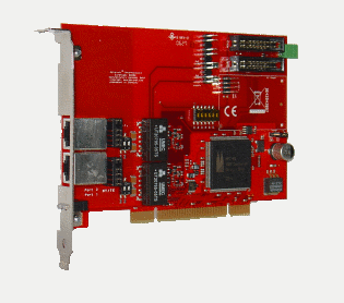
beroNet BN2S0 - 2 BRI ports
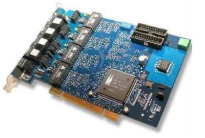
beroNet BN4S0 - 4 BRI ports
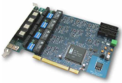
beroNet BN8S0 - 8 BRI ports
beroNet BN2S0 Specifications
Hardware Specifications:
* 2 BRI Ports each port can be configured separately to TE / NT mode
* Bridging in Hardware (for transparent voice,data and Fax transmission)
* PCM Bus (interconnection between BN cards to make hardware bridging possible across different cards)
* DTMF Tone Detection in Hardware
* all ports of the card can be fed independently by one external power supply unit (permitted in NT mode only; unit optional available)
* short circuit protection for the ISDN cabling by fuses (nonblowing,auto-recovery)
* line termination (100 Ù) is independently selectable for each port by DIP switch
* PCI interface is suitable for 3.3V as well as 5V PCI 2.2 slots (5V to 3.3V regulator on board)
Card size: 12.5 x 6.5 x 4.5 (cm)
Applications:
PC based PBX systems
BRI to VoIP Gateways
IVR Server
ISDN Monitoring and Recording
Least Cost Routing
beroNet BN4S0 Specifications
Hardware Specifications:
4 BRI Ports
each port can be configured individually for TE / NT mode
L1, L2, L3 tested (TE-Mode) for compliance to European standards for EuroISDN.
Hardware bridging (for transparent voice, data and fax transmission)
PCM Bus (inter-connection between BN cards to enable hardware bridging for different cards via optional PCM-Bus cable)
Hardware DTMF Detection
Software echo cancellation module, compliant to G.168-2000 and G.167 ITU-standards, works only for beroNet cards (available soon)
all ports can be powered individually by an power supply unit (except the BN8S0 only 4 ports can be powered, valid for NT mode only; optional unit available)
ISDN ports are short-circuit protected (by electronic fuse, auto-reset)
line termination (100 ohms) is selectable for each port by DIP switch
PCI interface is suitable for 3.3V as well as for 5V PCI 2.2 slots (5V to 3.3V on board regulator)
Card size: 12.5 x 6.5 x 4.5 (cm)
Applications:
PC based PBX systems
BRI to VoIP Gateways
IVR Server
ISDN Monitoring and Recording
Least Cost Routing
beroNet BN8S0 Specifications
Hardware Specifications:
8 BRI Ports
each port can be configured individually for TE / NT mode
L1, L2, L3 tested (TE-Mode) for compliance to European standards for EuroISDN.
Hardware bridging (for transparent voice, data and fax transmission)
PCM Bus (inter-connection between BN cards to enable hardware bridging for different cards via optional PCM-Bus cable)
Hardware DTMF Detection
Software echo cancellation module, compliant to G.168-2000 and G.167 ITU-standards, works only for beroNet cards (available soon)
all ports can be powered individually by an power supply unit (except the BN8S0 only 4 ports can be powered, valid for NT mode only; optional unit available)
ISDN ports are short-circuit protected (by electronic fuse, auto-reset)
line termination (100 ohms) is selectable for each port by DIP switch
PCI interface is suitable for 3.3V as well as for 5V PCI 2.2 slots (5V to 3.3V on board regulator)
Card size: 12.5 x 6.5 x 4.5 (cm)
Applications:
PC based PBX systems
BRI to VoIP Gateways
IVR Server
ISDN Monitoring and Recording
Least Cost Routing
BN2S0 and BN4S0 Hardware Installation
Attention: Please handle cards and modules with extreme caution, the parts are very delicate. Avoid static discharge at all cost.
Before you install the BN4S0 (or BN2S0), you should decide how to utilize the four (two) available ports. Determine which ports connect
to terminal equipment (TE mode) and which ports connect to the network (NT mode).
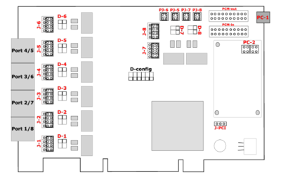
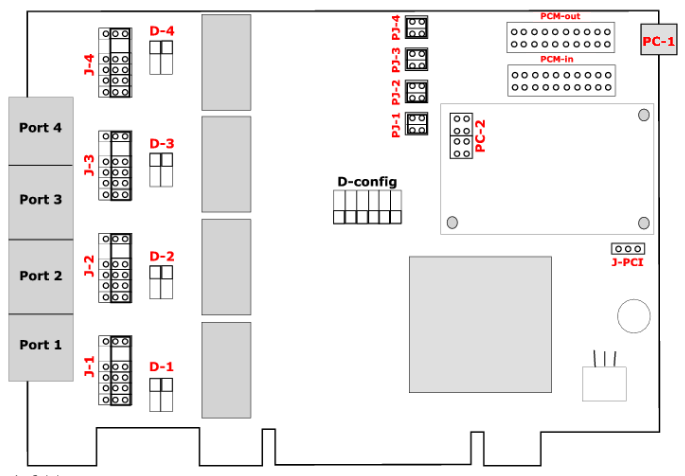
The schematic below shows a card with four ports, each with an adjacent group of jumpers and DIP-switches to the right.

Explanation of the jumpers, connectors and switches:
J1-J4 - A group of five jumpers determines the port type, NT or TE. If the jumpers short the two pins on the right (default setting), then the port is configured as "TE" (Terminal Equipment mode). If the jumpers connect the two pin on the left, the port is configured as "NT" (Terminal Network mode). Please note that a complete set of jumpers must be moved for each port.
PJ1-PJ4 - This group of pins must to be shorted (horizontally) if PC1 is connected to a BNPW1 power supply.
D1-D4 - The DIP switches are in the "on" position by default . This sets the terminal resistance to 100 Ohm. To change the terminal resistance, set the DIP switches to "off".
JPC - Jumper for PCI Voltage (3.3V / 5V). Default is 3.3V
PC1 - Powerconnector for BNPW1. If you are using this, all jumpers auf group PC2 has to be closed horizontally.
PC2 - Powerconnector for BNPW2
PCM-out & PCM-in - Connectors for the PCM bus. The PCM bus potentials to bridge calls in hardware across different beroNet cards which are connected over the PCM bus.
Attention: If you have an older motherboard, it is possible the PCI voltage is not detected automatically. Please set jumper PJ1 to the right position "3V3 reg." (the two pins on the right should be shorted).
After configuring the card according to your plan, you can install it in an empty PCI slot. Please follow these directions:
1. Turn off your PC.
2. Disconnect computer power completely by pulling the power cord from the wall socket.
3. Firmly insert the card into an empty PCI slot and tighten the screw. Use extreme care when inserting cards, so you do not damage components on it by touching other cards or the computer case.
4. Close the case, reconnect power and turn on the PC.
Note: No further settings are necessary to connect to ISDN circuits or ISDN devices. Any crossover is done with the jumpers on the card.
BN8S0 Hardware Installation
Attention: Please handle cards and modules with extreme caution, the parts are very delicate. Avoid static discharge at all cost.
Before you begin you should determine how to utilize the ports. Note that every RJ45 connector contains two ISDN ports. The BN8S0 comes with an Y-adapter cable. The connections must be split because two ISDN interfaces are combined into one port. Each end of the Y-cable has an RJ45 jack. If you want to connect ISDN telephones, please use straight RJ45 cables. The picture below shows the Y-cable port setup:
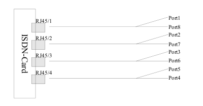
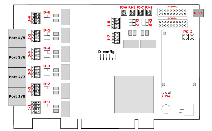
The jumpers and the DIP switches refer to two ISDN ports. They are color coded to each ISDN port. Note that the ports are counted from bottom to top, and the Jumper and Dip switches are present twice per RJ45 connector. Picture below shows the card with eight ports, each with an adjacent group of jumpers and DIP-switches to the right.
Explanation of the jumpers, connectors and switches:
J1-J8 - A group of five jumpers determines the port type, NT or TE. If the jumpers short the two pins on the right (the default setting), then the port is configured as "TE". If the jumpers connect the two pin on the left, the port is configured as "NT". Please note that a complete set of jumpers must be moved for each port.
PJ5-PJ6 - This group of pins must to be shorted (horizontally) if PC1 is connected to a BNPW1 power supply.
D1-D8 - The DIP switches are in the "on" position by default . This sets the terminal resistance to 100 Ohm. To change the terminal resistance, set the DIP switches to "off".
J-PCI - Jumper for PCI Voltage (3.3V / 5V). Default is 3.3V
PC1 - Powerconnector for BNPW1. If you are using this, all jumpers auf group PC2 has to be closed vertically.
PC2 - Powerconnector for BNPW2
PCMout & PCMin - Connectors for the PCM bus. The PCM bus potentials to bridge calls in hardware across different beroNet cards which are connected over the PCM bus.
Attention: If you have an older motherboard, it is possible the PCI voltage is not detected automatically. Please set jumper PJ1 to the right position "3V3 reg." (the two pins on the right should be shorted).
After configuring the card according to your plan, you can install it in an empty PCI slot. Please follow these directions:
1. Turn off your PC.
2. Disconnect computer power completely by pulling the power cord from the wall socket.
3. Firmly insert the card into an empty PCI slot and tighten the screw. Use extreme care when inserting cards, so you do not damage components on it by touching other cards or the computer case.
4. Close the case, reconnect power and turn on the PC.
Note: No further settings are necessary to connect to ISDN circuits or ISDN devices. Any crossover is done with the jumpers on the card.
mISDN configuration
As we already mentioned beroNet's BRI cards runs with mISDN channel driver. In order to use these cards we recommend you to read our tutorial for mISDN installation. When ready with this install the mISDN (modular ISDN) drivers as is shown in our tutorial. When ready with this come back here and you'll learn how to configure the beroNet's card.
Prerequisites
The mISDN kernel driver module must be loaded in order the chan_misdn can utilized.
Compiled Asterisk server with chan_misdn support.
Properly hardware installed beroNet's card(s).
There are two ways of detecting, configuring and loading the driver modules. One is to load everything by hand, the other is to use the 'misdn-init' script. The first method is considered obsolete, and is useful only for very specific tasks. This tutorial is mainly for the installation and the configuration of the beroNet's cards, and doesn't not claim to explore the ways of manual loading of the drivers. That's why we are going to descibe only the 'misdn-init' script.
We will explore the capabilities of misdn-init on the next page.
misdn-init
Warning: Running misdn-init is not recommended while an Asterisk server is running. You should stop Asterisk server either by asterisk -rx "stop now" or asterisk -rx "stop gracefully".
Detecting the card
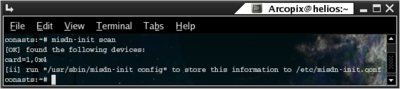
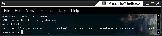
In order to detect the current cards that supports mISDN you should use the misdn-init script with `scan` suffix. (Run misdn-init scan).
When you run this command the script will scan for the current available hardware. Here is a sample output:
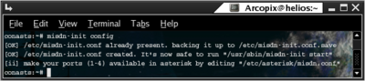
Configuring the cards
In order to create automatic configuration file for misdn modules you should run misdn-init script with `config` suffix. (Run misdn-init config). Here is a sample output:
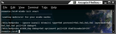
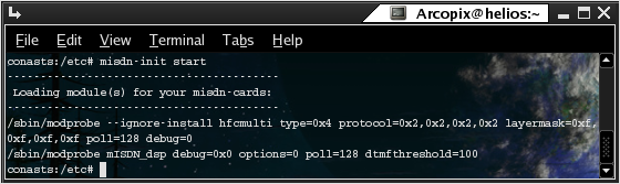
Starting mISDN support
In order to load the drivers according to the configuration for misdn support you should run misdn-init script with `start` suffix. (Run misdn-init start). Here is a sample output:
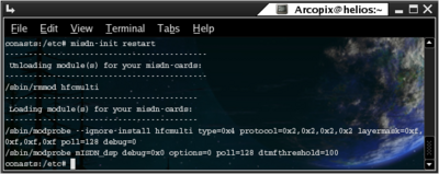
Restarting mISDN support
In order to reload the drivers according to the configuration for misdn support you should run misdn-init script with `restart` suffix. (Run misdn-init restart). This command will stop the support and then will attempt to load up the devices' drivers. Here is a sample output:
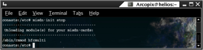
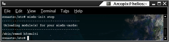
Stopping mISDN support
In order to unload the drivers according to the configuration for misdn support you should run misdn-init script with `stop` suffix. (Run misdn-init stop). Here is a sample output:
Configuration files
In order to run properly the beroNet's card(s) it is recommended to be familiar with the configuration files that are related to that setup. Configuration files that are related to that setup are:
misdn-init.conf (defaultly located at /etc/ directory)
misdn.conf (defaultly located at /etc/asterisk/ directory)
extensions.conf (defaultly located at /etc/asterisk/ directory)
On the following pages we will explain their main purpose and relations to the beroNet's card(s) utilization.
misdn-init.conf
The misdn-init.conf is been generated by the misdn-init script. However you might need to edit some option by hand.
This configuration file is assembled by four parts: Card Settings, Port settings, Port Options and General Options for your hfcmulti hardware. We will descibe all those sections.
Card Settings - with this settings you will be able to set up more than one cards with different options.
Syntax: card=<number>,<type>[,<option>...]
Example:
card=1,0x4
card=2,0x2
card=3,0x4
Port settings - with this settings you can set the working mode for each port on your cards:
Syntax: <port_type>=<port_number>[,<port_number>...]
Example:
te_ptmp=1,2
nt_ptp=3
nt_ptmp=4
Port Options - use this setting in order to configure essential clocking features.
Syntax: option=<port_number>,<option>[,<option>...]
Example:
option=1,master_clock
option=2,ais,nocrc4
option=3,optical,los,ais,slip
General Options for your hfcmulti hardware - there are number of special options for the hfcmulti hardware.
Example:
poll=128
dsp_poll=128
dsp_options=0
dtmfthreshold=100
debug=0
misdn.conf
See section 3 of chan_misdn tutorial.
extensions.conf
The configuration file named extensions.conf which is located in the Asterisk configuration directory (/etc/asterisk) defines the Asterisk's dialplan logic. This tutorial does not claim to give you an understanding on extension.conf syntax or applications. In this section we will just give you some examples how you can use the BRI hardware in your dialplan. We will use the Dial and ChanIsAvail applications. In order to dial through the BRI channels you should use the Dial application in one of the following ways:
Examples:
You can use ChanIsAvail application in order to check if the certain channel is available.
CLI commands
There are number of CLI commands which will be useful while you set up / monitor / debug mISDN channels.
misdn show config - Shows the present configuration for all misdn ports / channels.
misdn reload - Command, for reconfiguration of the chan_misdn module. This will be executed with a global reload of the Asterisk.
misdn show channels - Shows a list of all active mISDN channels.
misdn show fullstacks - Shows the status of the ports and the channelstatus.
misdn show stacks - Shows only the status of the ports.
misdn set debug <debuglevel> - Determines the precision of the debug-output. The following values are possible:
misdn send display <channel> <msg> - It sends a so called display message to the prescribed channel. If the connected terminal device is capable of displaying the message then the message will appear on the screen of the device.
Links
Channel mISDN (chan_misdn) installation and configuration
Asterisk's Official Web Site
beroNet's Official Web Site
configuration-BN4S0.tar
mISDN Official Web Page
beroNet offers the BN2S0, BN4S0 and the BN8S0 BRI ISDN cards, a powerful and flexible solution for the Open Source PBX Asterisk.
The BNXS0 card series is available with 2, 4 or 8 S0 ports, which can be configured individually for each port for NT (Network Termination) or for TE (Terminal Equipment) mode. In either mode the card supports Point-To-Multi-Point mode or Point-To-Point mode. You can power each port (except BN8S0) with our power supply module (BN-Power) to provide current to your Terminal Equipment.
On the following pages we will describe the hardware specifications of beroNet cards:
beroNet BN2S0 - 2 BRI ports
beroNet BN4S0 - 4 BRI ports
beroNet BN8S0 - 8 BRI ports
beroNet BN2S0 Specifications
Hardware Specifications:
* 2 BRI Ports each port can be configured separately to TE / NT mode
* Bridging in Hardware (for transparent voice,data and Fax transmission)
* PCM Bus (interconnection between BN cards to make hardware bridging possible across different cards)
* DTMF Tone Detection in Hardware
* all ports of the card can be fed independently by one external power supply unit (permitted in NT mode only; unit optional available)
* short circuit protection for the ISDN cabling by fuses (nonblowing,auto-recovery)
* line termination (100 Ù) is independently selectable for each port by DIP switch
* PCI interface is suitable for 3.3V as well as 5V PCI 2.2 slots (5V to 3.3V regulator on board)
Card size: 12.5 x 6.5 x 4.5 (cm)
Applications:
PC based PBX systems
BRI to VoIP Gateways
IVR Server
ISDN Monitoring and Recording
Least Cost Routing
beroNet BN4S0 Specifications

Hardware Specifications:
4 BRI Ports
each port can be configured individually for TE / NT mode
L1, L2, L3 tested (TE-Mode) for compliance to European standards for EuroISDN.
Hardware bridging (for transparent voice, data and fax transmission)
PCM Bus (inter-connection between BN cards to enable hardware bridging for different cards via optional PCM-Bus cable)
Hardware DTMF Detection
Software echo cancellation module, compliant to G.168-2000 and G.167 ITU-standards, works only for beroNet cards (available soon)
all ports can be powered individually by an power supply unit (except the BN8S0 only 4 ports can be powered, valid for NT mode only; optional unit available)
ISDN ports are short-circuit protected (by electronic fuse, auto-reset)
line termination (100 ohms) is selectable for each port by DIP switch
PCI interface is suitable for 3.3V as well as for 5V PCI 2.2 slots (5V to 3.3V on board regulator)
Card size: 12.5 x 6.5 x 4.5 (cm)
Applications:
PC based PBX systems
BRI to VoIP Gateways
IVR Server
ISDN Monitoring and Recording
Least Cost Routing
beroNet BN8S0 Specifications

Hardware Specifications:
8 BRI Ports
each port can be configured individually for TE / NT mode
L1, L2, L3 tested (TE-Mode) for compliance to European standards for EuroISDN.
Hardware bridging (for transparent voice, data and fax transmission)
PCM Bus (inter-connection between BN cards to enable hardware bridging for different cards via optional PCM-Bus cable)
Hardware DTMF Detection
Software echo cancellation module, compliant to G.168-2000 and G.167 ITU-standards, works only for beroNet cards (available soon)
all ports can be powered individually by an power supply unit (except the BN8S0 only 4 ports can be powered, valid for NT mode only; optional unit available)
ISDN ports are short-circuit protected (by electronic fuse, auto-reset)
line termination (100 ohms) is selectable for each port by DIP switch
PCI interface is suitable for 3.3V as well as for 5V PCI 2.2 slots (5V to 3.3V on board regulator)
Card size: 12.5 x 6.5 x 4.5 (cm)
Applications:
PC based PBX systems
BRI to VoIP Gateways
IVR Server
ISDN Monitoring and Recording
Least Cost Routing
BN2S0 and BN4S0 Hardware Installation
Attention: Please handle cards and modules with extreme caution, the parts are very delicate. Avoid static discharge at all cost.
Before you install the BN4S0 (or BN2S0), you should decide how to utilize the four (two) available ports. Determine which ports connect
to terminal equipment (TE mode) and which ports connect to the network (NT mode).
The schematic below shows a card with four ports, each with an adjacent group of jumpers and DIP-switches to the right.
Explanation of the jumpers, connectors and switches:
J1-J4 - A group of five jumpers determines the port type, NT or TE. If the jumpers short the two pins on the right (default setting), then the port is configured as "TE" (Terminal Equipment mode). If the jumpers connect the two pin on the left, the port is configured as "NT" (Terminal Network mode). Please note that a complete set of jumpers must be moved for each port.
PJ1-PJ4 - This group of pins must to be shorted (horizontally) if PC1 is connected to a BNPW1 power supply.
D1-D4 - The DIP switches are in the "on" position by default . This sets the terminal resistance to 100 Ohm. To change the terminal resistance, set the DIP switches to "off".
JPC - Jumper for PCI Voltage (3.3V / 5V). Default is 3.3V
PC1 - Powerconnector for BNPW1. If you are using this, all jumpers auf group PC2 has to be closed horizontally.
PC2 - Powerconnector for BNPW2
PCM-out & PCM-in - Connectors for the PCM bus. The PCM bus potentials to bridge calls in hardware across different beroNet cards which are connected over the PCM bus.
Attention: If you have an older motherboard, it is possible the PCI voltage is not detected automatically. Please set jumper PJ1 to the right position "3V3 reg." (the two pins on the right should be shorted).
After configuring the card according to your plan, you can install it in an empty PCI slot. Please follow these directions:
1. Turn off your PC.
2. Disconnect computer power completely by pulling the power cord from the wall socket.
3. Firmly insert the card into an empty PCI slot and tighten the screw. Use extreme care when inserting cards, so you do not damage components on it by touching other cards or the computer case.
4. Close the case, reconnect power and turn on the PC.
Note: No further settings are necessary to connect to ISDN circuits or ISDN devices. Any crossover is done with the jumpers on the card.
BN8S0 Hardware Installation
Attention: Please handle cards and modules with extreme caution, the parts are very delicate. Avoid static discharge at all cost.
Before you begin you should determine how to utilize the ports. Note that every RJ45 connector contains two ISDN ports. The BN8S0 comes with an Y-adapter cable. The connections must be split because two ISDN interfaces are combined into one port. Each end of the Y-cable has an RJ45 jack. If you want to connect ISDN telephones, please use straight RJ45 cables. The picture below shows the Y-cable port setup:
The jumpers and the DIP switches refer to two ISDN ports. They are color coded to each ISDN port. Note that the ports are counted from bottom to top, and the Jumper and Dip switches are present twice per RJ45 connector. Picture below shows the card with eight ports, each with an adjacent group of jumpers and DIP-switches to the right.
Explanation of the jumpers, connectors and switches:
J1-J8 - A group of five jumpers determines the port type, NT or TE. If the jumpers short the two pins on the right (the default setting), then the port is configured as "TE". If the jumpers connect the two pin on the left, the port is configured as "NT". Please note that a complete set of jumpers must be moved for each port.
PJ5-PJ6 - This group of pins must to be shorted (horizontally) if PC1 is connected to a BNPW1 power supply.
D1-D8 - The DIP switches are in the "on" position by default . This sets the terminal resistance to 100 Ohm. To change the terminal resistance, set the DIP switches to "off".
J-PCI - Jumper for PCI Voltage (3.3V / 5V). Default is 3.3V
PC1 - Powerconnector for BNPW1. If you are using this, all jumpers auf group PC2 has to be closed vertically.
PC2 - Powerconnector for BNPW2
PCMout & PCMin - Connectors for the PCM bus. The PCM bus potentials to bridge calls in hardware across different beroNet cards which are connected over the PCM bus.
Attention: If you have an older motherboard, it is possible the PCI voltage is not detected automatically. Please set jumper PJ1 to the right position "3V3 reg." (the two pins on the right should be shorted).
After configuring the card according to your plan, you can install it in an empty PCI slot. Please follow these directions:
1. Turn off your PC.
2. Disconnect computer power completely by pulling the power cord from the wall socket.
3. Firmly insert the card into an empty PCI slot and tighten the screw. Use extreme care when inserting cards, so you do not damage components on it by touching other cards or the computer case.
4. Close the case, reconnect power and turn on the PC.
Note: No further settings are necessary to connect to ISDN circuits or ISDN devices. Any crossover is done with the jumpers on the card.
mISDN configuration
As we already mentioned beroNet's BRI cards runs with mISDN channel driver. In order to use these cards we recommend you to read our tutorial for mISDN installation. When ready with this install the mISDN (modular ISDN) drivers as is shown in our tutorial. When ready with this come back here and you'll learn how to configure the beroNet's card.
Prerequisites
The mISDN kernel driver module must be loaded in order the chan_misdn can utilized.
Compiled Asterisk server with chan_misdn support.
Properly hardware installed beroNet's card(s).
There are two ways of detecting, configuring and loading the driver modules. One is to load everything by hand, the other is to use the 'misdn-init' script. The first method is considered obsolete, and is useful only for very specific tasks. This tutorial is mainly for the installation and the configuration of the beroNet's cards, and doesn't not claim to explore the ways of manual loading of the drivers. That's why we are going to descibe only the 'misdn-init' script.
We will explore the capabilities of misdn-init on the next page.
misdn-init
Warning: Running misdn-init is not recommended while an Asterisk server is running. You should stop Asterisk server either by asterisk -rx "stop now" or asterisk -rx "stop gracefully".
Detecting the card
In order to detect the current cards that supports mISDN you should use the misdn-init script with `scan` suffix. (Run misdn-init scan).
When you run this command the script will scan for the current available hardware. Here is a sample output:
Configuring the cards
In order to create automatic configuration file for misdn modules you should run misdn-init script with `config` suffix. (Run misdn-init config). Here is a sample output:

Starting mISDN support
In order to load the drivers according to the configuration for misdn support you should run misdn-init script with `start` suffix. (Run misdn-init start). Here is a sample output:
Restarting mISDN support
In order to reload the drivers according to the configuration for misdn support you should run misdn-init script with `restart` suffix. (Run misdn-init restart). This command will stop the support and then will attempt to load up the devices' drivers. Here is a sample output:

Stopping mISDN support
In order to unload the drivers according to the configuration for misdn support you should run misdn-init script with `stop` suffix. (Run misdn-init stop). Here is a sample output:
Configuration files
In order to run properly the beroNet's card(s) it is recommended to be familiar with the configuration files that are related to that setup. Configuration files that are related to that setup are:
misdn-init.conf (defaultly located at /etc/ directory)
misdn.conf (defaultly located at /etc/asterisk/ directory)
extensions.conf (defaultly located at /etc/asterisk/ directory)
On the following pages we will explain their main purpose and relations to the beroNet's card(s) utilization.
misdn-init.conf
The misdn-init.conf is been generated by the misdn-init script. However you might need to edit some option by hand.
This configuration file is assembled by four parts: Card Settings, Port settings, Port Options and General Options for your hfcmulti hardware. We will descibe all those sections.
Card Settings - with this settings you will be able to set up more than one cards with different options.
Syntax: card=<number>,<type>[,<option>...]
<number> - you should count your cards beginning with 1 (so the third card will be with 3)
<type> - either 0x1,0x4 or 0x8 for your hfcmulti hardware, or the name of your card driver module.
<option> - here you can add some options for the different cards. Valid options are:
<type> - either 0x1,0x4 or 0x8 for your hfcmulti hardware, or the name of your card driver module.
<option> - here you can add some options for the different cards. Valid options are:
ulaw - uLaw (instead of aLaw)
dtmf - enable DTMF detection on all B-channels
pcm_slave - set PCM bus into slave mode. If you have a set of cards, all wired via PCM. Set all cards into pcm_slave mode and leave one out. The left card will automatically be Master.
ignore_pcm_frameclock - this can be set in conjunction wit pcm_slave. If this card has a PCI Bus Position before the Position of the Master, then this port cannot yet receive a frameclock, so it must ignore the pcm frameclock.
rxclock - use clocking for pcm from ST Port
crystalclock - use clocking for pcm from PLL (genrated on board)
watchdog - This dual E1 Board has a Watchdog for transparent mode
Example:
card=1,0x4
card=2,0x2
card=3,0x4
Port settings - with this settings you can set the working mode for each port on your cards:
Syntax: <port_type>=<port_number>[,<port_number>...]
<port_type> - the port type can be set via this option
<port_number> port that should be considered
te_ptp - for TE (Terminal Equipment) mode, PTP settings
te_ptmp - for TE (Terminal Equipment) mode, PTMP settings
te_capi_ptp - for TE (Terminal Equipment) mode (CAPI), PTP settings
te_capi_ptmp - for TE (Terminal Equipment) mode (CAPI), PTMP settings
nt_ptp - for NT (Network Termination) mode, PTP settings
nt_ptmp - for NT (Network Termination) mode, PTMP settings
<port_number> port that should be considered
Example:
te_ptmp=1,2
nt_ptp=3
nt_ptmp=4
Port Options - use this setting in order to configure essential clocking features.
Syntax: option=<port_number>,<option>[,<option>...]
<option> - type of the clocking
* The master_clock option is essential for retrieving and transmitting faxes to avoid failures during transmission. It tells the driver to synchronize the Card with the given Port which should be a TE Port and connected to the PSTN in general.
master_clock* - use master clock for this S/T interface (only once per chip, only for HFC 8/4)
optical - optical (only HFC-E1)
los - report LOS (only HFC-E1)
ais - report AIS (only HFC-E1)
slip - report SLIP (only HFC-E1)
nocrc4 - turn off crc4 mode use double frame instead (only HFC-E1)
optical - optical (only HFC-E1)
los - report LOS (only HFC-E1)
ais - report AIS (only HFC-E1)
slip - report SLIP (only HFC-E1)
nocrc4 - turn off crc4 mode use double frame instead (only HFC-E1)
* The master_clock option is essential for retrieving and transmitting faxes to avoid failures during transmission. It tells the driver to synchronize the Card with the given Port which should be a TE Port and connected to the PSTN in general.
Example:
option=1,master_clock
option=2,ais,nocrc4
option=3,optical,los,ais,slip
General Options for your hfcmulti hardware - there are number of special options for the hfcmulti hardware.
poll=<number>
You should define only one poll value. You cannot set a specific poll for different cards. The poll number represents the number of samples for each fifo (First in, First out) process. By default 128 is used, but by decreasing the poll you will reduce the delay and the cpu load. If you are unsure, don't use this option. Valid settings are: 32, 64, 128, 256.
dsp_poll=<number> This is the poll option which is used by mISDN_dsp, this might differ from the one given by poll= for the hfc based cards, since they can only use multiples of 32. The dsp_poll is dependant on the kernel timer setting which can be found in the CPU section in the kernel config. Defaults are there either 100Hz, 250Hz or 1000Hz. If your setting is either 1000 or 250 it is compatible with the poll option for the hfc chips, if you have 100 - it is different and you need here a multiple of 80. The default is to have no dsp_poll option, then the dsp itself finds out which option is the best to use by itself. Again, if you are unsure, don't use this option.
pcm=<number>By using this option you can specify the id of the PCM bus. All PCM busses with the same ID are expected to be connected and have equal slots. Only one chip of the PCM bus must be master, the others slave.
debug=<number>By using this option you can enable or disable debugging (see hfc_multi.h for debug options).
dsp_options=<number>By setting this option to 2, you'll have software bridging instead of hardware bridging.
dtmfthreshold=<milliseconds>Here you can tune the sensitivity of the dtmf tone recognizer.
timer=<1|0>Set this to 1 if you want hfcmulti to register at ztdummy (zaptel) and provide a 1khz timing source for it. This makes it possible to have an accurate timing source for Asterisk through zaptel from hfcmulti to make applications like Meetme and faxing between wctdm and hfcmulti work properly.
Example:
poll=128
dsp_poll=128
dsp_options=0
dtmfthreshold=100
debug=0
misdn.conf
See section 3 of chan_misdn tutorial.
extensions.conf
The configuration file named extensions.conf which is located in the Asterisk configuration directory (/etc/asterisk) defines the Asterisk's dialplan logic. This tutorial does not claim to give you an understanding on extension.conf syntax or applications. In this section we will just give you some examples how you can use the BRI hardware in your dialplan. We will use the Dial and ChanIsAvail applications. In order to dial through the BRI channels you should use the Dial application in one of the following ways:
Dial(mISDN/g:<groupname_in_misdn.conf>/<numbertodial>) ; In this way Asterisk will dial number <numbertodial> on the first line available in the group called <groupname_in_misdn.conf>. (the section called [<groupname_in_misdn.conf>] in misdn.conf).
Dial(mISDN/<portnumber>/<numbertodial>) ; In this way Asterisk will dial number <numbertodial> through the <portnumber> port.
Dial(mISDN/<portnumber>/<numbertodial>) ; In this way Asterisk will dial number <numbertodial> through the <portnumber> port.
Examples:
exten =>123,dial(mISDN/g:groupX/0900900) ; This will dial 0900900 through group named groupX
exten =>456,dial(mISDN/2/0900800) ; This will dial 0900800 through port two (channel two) defined in misdn.conf
exten =>456,dial(mISDN/2/0900800) ; This will dial 0900800 through port two (channel two) defined in misdn.conf
You can use ChanIsAvail application in order to check if the certain channel is available.
CLI commands
There are number of CLI commands which will be useful while you set up / monitor / debug mISDN channels.
misdn show config - Shows the present configuration for all misdn ports / channels.
misdn reload - Command, for reconfiguration of the chan_misdn module. This will be executed with a global reload of the Asterisk.
misdn show channels - Shows a list of all active mISDN channels.
misdn show fullstacks - Shows the status of the ports and the channelstatus.
misdn show stacks - Shows only the status of the ports.
misdn set debug <debuglevel> - Determines the precision of the debug-output. The following values are possible:
0 - no Debug
1 - mISDN and Asterisk Messages and all Statuschanges
2 - mISDN Messages with specific Information (i.e. bearer capability) /plus Messages from level 1/
3 very communicative, as Level 2 + many additional Driverinformation /plus Messages from level 1 and 2/
4 even more communicative than Level 3 /plus Messages from level 1, 2 and 3/
misdn send display <channel> <msg> - It sends a so called display message to the prescribed channel. If the connected terminal device is capable of displaying the message then the message will appear on the screen of the device.
Links
Channel mISDN (chan_misdn) installation and configuration
Asterisk's Official Web Site
beroNet's Official Web Site
configuration-BN4S0.tar
mISDN Official Web Page
| Add Comment |
Latest Headlines:
-
T.38 faxing with Zoiper 2.15 is now easier than ever
section: voip software
-
Asterisk 1.4.21 Released
section: Asterisk
-
Asterisk 1.4.20 Released
section: Asterisk
-
Asterisk 1.4.20-rc2 Released
section: Asterisk
-
Asterisk 1.4.20-rc1 Now Available
section: Asterisk
- News Archives (older news)
Latest Tutorials:
-
Sending Fax from Zoiper to Zoiper using T.38
added 08/Dec/2008 18:16
-
VMAuthenticate (dialplan application)
added 01/Mar/2008 15:57
-
Siptronic ST-530
added 06/Nov/2007 17:57
-
Siemens C455 IP hardphone
added 05/Nov/2007 10:24
-
Zoiper
added 22/Oct/2007 17:53
Latest Comments:
-
God bless Dr. Aba for his marvelous work...
tutorial: Siptronic ST-530
-
https://raindrop.io/komalkashyap4564/hea...
tutorial: SIP with NAT or Firewalls
-
https://raindrop.io/komalkashyap4564/hea...
tutorial: SIP with NAT or Firewalls
-
https://raindrop.io/komalkashyap4564/hea...
tutorial: SIP with NAT or Firewalls
-
https://raindrop.io/komalkashyap4564/hea...
tutorial: SIP with NAT or Firewalls